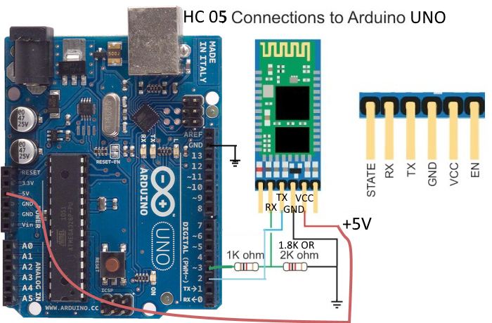

The processor uses it's own TX pin to send a signal to the USB-to-serial adapter's RX pin. The communication is two-way, so the Arduino's processor can send signals back to the USB-to-serial adapter. The TX wire from your USB-to-serial adapter rapidly switches between 0 and 5 volts in a pattern, and it is attached to the RX pin on the Arduino's processor, which is listening to those patterns. The TX wire or pin transmits data to another device.

The most important ones are called RX (short for receive) and TX (short for transmit).Īs the name implies, the RX wire or pin receives from another device. There are several wires or connections involved with serial communication. The external adapters are very often called FTDI adapters, even if the brand of chip is not FTDI. Some Arduinos, such as the LilyPad, Mini, and Pro Mini, don't come with a USB-to-serial adapter and you need to supply your own external one. Most Arduinos have a USB-to-serial adapter chip built-in, so you can connect the Arduino directly to your computer without any special interface or programmer. The version of this RS-232 protocol that is compatible with voltages in the range the Arduino processor can handle is called TTL serial, or sometimes you may hear it called TTL-232, or just serial. The ATMEL processor on an Arduino uses signals in the 0 to 5 volt range. A PC with such an interface typically uses voltages that swing between 12 to -12 volts to send an RS-232 signal. Personal computers typically no longer come with RS-232 interfaces, but they used to a few years ago. RS-232 communications use voltages that change rapidly from a positive voltage of 3 to 25 volts, to a negative voltage of -3 to -25 volts. It is based on an old communication protocol called RS-232. This serial programming uses a protocol called TTL serial. As the bootloader program receives the sketch, it stores into the lower portion of Flash memory. The bootloader actually resides in a small portion of the Flash memory in the upper range of memory addresses, which is reserved for bootloader use. In order for the Arduino to accept a sketch from the serial interface, it runs a program called a bootloader, which accepts the sketch and writes it into Flash memory. The USB-to-serial chip interfaces with the UART interface of the ATMEL processor on your Arduino. In Arduino land, USB-to-serial chips are used to interface a computer running the Arduino IDE to your Arduino's main processor for uploading new sketches and for interacting with your sketches via a serial monitor window. The FTDI company specializes in chips used to connect via USB.


 0 kommentar(er)
